Machine Vision
Robot Positioning
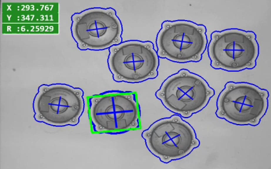
We measure the part's position and angle deviation from a reference sample with 2D or 3D cameras and pass it to the robot as an offset for every part.
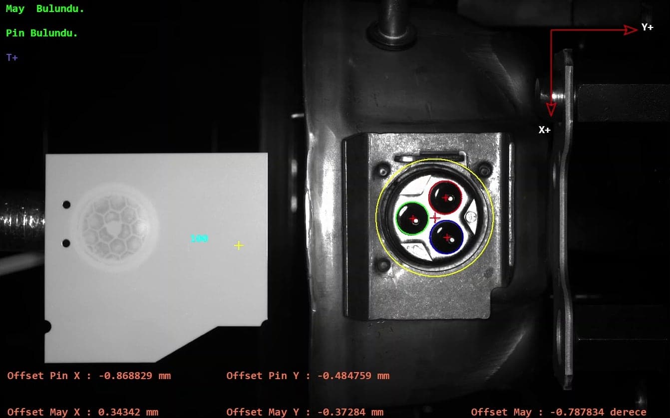
In serial production a part never stops at exactly the same point; even a few millimeters of shift can make the robot grip at the wrong point or place the part incorrectly. In robot positioning the camera measures the part's actual position and angle and the robot program is corrected for every part, reducing the need for costly fixtures and precise feeders.
We apply the correction as an offset relative to a reference sample. During setup, a common zero point is defined for the camera and the robot using the reference part, and the two are calibrated to each other at this point. For every following part, the camera measures the position deviation in X and Y and the rotation relative to the reference; these values are sent to the robot as an offset, and the robot corrects its taught motion accordingly.
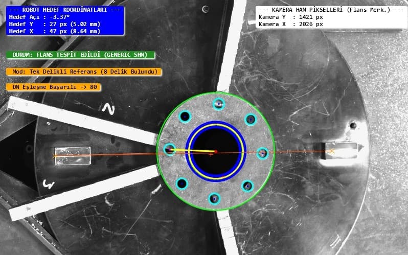
The image on this page is the screen of a machine tending cell we built: the camera finds the pin and a reference feature on the part and sends the X–Y position deviation in millimeters and the rotation in degrees to the robot. In our flange recognition application, the robot's target position and angle are calculated the same way.
Highlights
- Offset relative to a reference sample
- Common zero point for camera and robot
- X, Y and angle correction
- Less need for fixtures
- 2D and 3D camera options
Application areas
- Machine tending
- Flanges & metal parts
- Random part picking
- Glassware picking